LoRaWAN Wireless Sensor Network Protocol
What are LoRa and LoRaWAN?
In this page, you’ll learn why LoRaWAN is so awesome, hear about some great LoRaWAN use cases, and learn the difference between LoRa and LoRaWAN.
LoRa
LoRa is a wireless modulation technique derived from Chirp Spread Spectrum (CSS) technology. It encodes information on radio waves using chirp pulses - similar to the way dolphins and bats communicate! LoRa modulated transmission is robust against disturbances and can be received across great distances.
Don’t be alarmed about the complex terms; LoRa modulation and Chirp Spread Spectrum technology are simple to understand in practice. In case you are curious, in this video, Richard Wenner explains how Chirp Spread Spectrum technology works:
LoRa is ideal for applications that transmit small chunks of data with low bit rates. Data can be transmitted at a longer range compared to technologies like WiFi, Bluetooth or ZigBee. These features make LoRa well suited for sensors and actuators that operate in low power mode.
LoRa can be operated on the license free sub-gigahertz bands, for example, 915 MHz, 868 MHz, and 433 MHz. It also can be operated on 2.4 GHz to achieve higher data rates compared to sub-gigahertz bands, at the cost of range. These frequencies fall into ISM bands that are reserved internationally for industrial, scientific, and medical purposes.
LoRaWAN
LoRaWAN is a Media Access Control (MAC) layer protocol built on top of LoRa modulation. It is a software layer which defines how devices use the LoRa hardware, for example when they transmit, and the format of messages.
The LoRaWAN protocol is developed and maintained by the LoRa Alliance. The first LoRaWAN specification was released in January 2015. The table below shows the version history of the LoRaWAN specifications. At the time of this writing the latest specifications are 1.0.4 (in 1.0 series) and 1.1 (1.1 series).
| Version | Release date |
| 1.0 | January 2015 |
| 1.0.1 | February 2016 |
| 1.0.2 | July 2016 |
| 1.1 | October 2017 |
| 1.0.3 | July 2018 |
| 1.0.4 | October 2020 |
Bandwidth vs. Range
LoRaWAN is suitable for transmitting small size payloads (like sensor data) over long distances. LoRa modulation provides a significantly greater communication range with low bandwidths than other competing wireless data transmission technologies. The following figure shows some access technologies that can be used for wireless data transmission and their expected transmission ranges vs. bandwidth.

Why is LoRaWAN so awesome?
- Ultra low power - LoRaWAN end devices are optimized to operate in low power mode and can last up to 10 years on a single coin cell battery.
- Long range - LoRaWAN gateways can transmit and receive signals over a distance of over 10-15 kilometers in rural areas and up to 3 kilometers in dense urban areas.
- Deep indoor penetration - LoRaWAN networks can provide deep indoor coverage, and easily cover multi floor buildings.
- License free spectrum - You don’t have to pay expensive frequency spectrum license fees to deploy a LoRaWAN network.
- Geolocation- A LoRaWAN network can determine the location of end devices using triangulation without the need for GPS. A LoRa end device can be located if at least three gateways pick up its signal.
- High capacity - LoRaWAN Network Servers handle millions of messages from thousands of gateways.
- Public and private deployments - It is easy to deploy public and private LoRaWAN networks using the same hardware (gateways, end devices, antennas) and software (UDP packet forwarders, Basic Station software, LoRaWAN stacks for end devices).
- End-to-end security- LoRaWAN ensures secure communication between the end device and the application server using AES-128 encryption.
- Firmware updates over the air - You can remotely update firmware (applications and the LoRaWAN stack) for a single end device or group of end devices.
- Roaming- LoRaWAN end devices can perform seamless handovers from one network to another.
- Low cost - Minimal infrastructure, low-cost end nodes and open source software.
- Certification program- The LoRa Alliance certification program certifies end devices and provides end-users with confidence that the devices are reliable and compliant with the LoRaWAN specification.
- Ecosystem- LoRaWAN has a very large ecosystem of device makers, gateway makers, antenna makers, network service providers, and application developers.
LoRaWAN use cases
Here are a few great LoRaWAN use cases provided by Semtech, to give you some insight into how LoRaWAN can be applied:
- Vaccine cold chain monitoring - LoRaWAN sensors are used to ensure vaccines are kept at appropriate temperatures in transit.
- Animal conservation - Tracking sensors manage endangered species such as Black Rhinos and Amur Leopards.
- Dementia patients - Wristband sensors provide fall detection and medication tracking.
- Smart farms- Real time insights into crop soil moisture and optimized irrigation schedule reduce water use up to 30%.
- Water conservation- Identification and faster repair of leaks in a city’s water network.
- Food safety- Temperature monitoring ensures food quality maintenance.
- Smart waste bins - Waste bin level alerts sent to staff optimize the pickup schedule.
- Smart bikes- Bike trackers track bikes in remote areas and dense buildings.
- Airport tracking - GPS-free tracking monitors vehicles, personnel, and luggage.
- Efficient workspaces - Room occupancy, temperature, energy usage and parking availability monitoring.
- Cattle health - Sensors monitor cattle health, detect diseases and forecast calves delivery time.
- LoRa in space - Satellites to provide LoRaWAN-based coverage worldwide.
LoRa Alliance
The LoRa Alliance® is an open, non-profit association established in 2015. It supports development of the LoRaWAN protocol and ensures interoperability of all LoRaWAN products and technologies. Today, the LoRa Alliance has over 500 members around the globe.
The LoRa Alliance provides LoRaWAN certification for end devices. Certified end devices provide users with confidence that the end device is reliable and compliant with the LoRaWAN specification. You can learn more about LoRaWAN certification by visiting the LoRa Alliance website. Certification is only available for device manufacturers that are members of the LoRa Alliance. Once certified, the manufacturer can use the LoRaWAN Certified mark with the product.
LoRaWAN is now an ITU standard.
As announced by the LoRa Alliance® on December 7, 2021, LoRaWAN® is officially approved as a standard for Low Power Wide Area Networking (LPWAN) by the International Telecommunication Union (ITU).
Read the Lora Alliance® Press Release, LoRaWAN® Formally Recognized as ITU International Standard for Low Power Wide Area Networking for more information.
LoRaWAN Architecture
LoRaWAN networks are deployed in a star-of-stars topology.
A typical LoRaWAN network consists of the following elements.
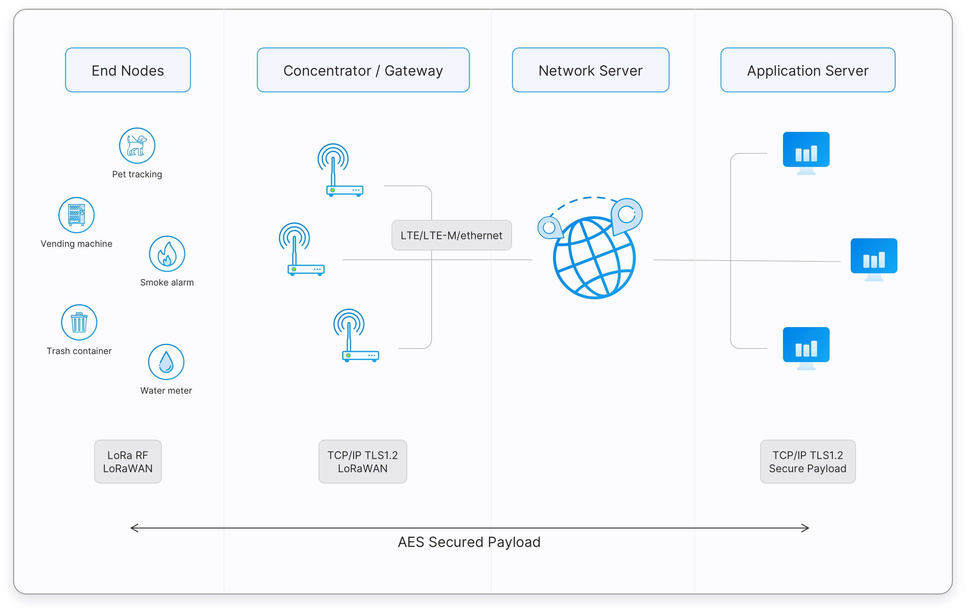 Figure: A typical LoRaWAN network architecture
-
End Devices - sensors or actuators send LoRa modulated wireless messages to the gateways or receive messages wirelessly back from the gateways. .
-
Gateways - receive messages from end devices and forward them to the Network Server.
-
Network Server - a piece of software running on a server that manages the entire network.
-
Application servers - a piece of software running on a server that is responsible for securely processing application data.
-
Join Server - a piece of software running on a server that processes join-request messages sent by end devices (The Join Server is not shown in the above figure).
End devices communicate with nearby gateways and each gateway is connected to the network server. LoRaWAN networks use an ALOHA based protocol, so end devices don’t need to peer with specific gateways. Messages sent from end devices travel through all gateways within range. These messages are received by the Network Server. If the Network Server has received multiple copies of the same message, it keeps a single copy of the message and discards others. This is known as message deduplication.
Let’s examine each element of the LoRaWAN network in detail.
End devices
A LoRaWAN end device can be a sensor, an actuator, or both. They are often battery operated. These end devices are wirelessly connected to the LoRaWAN network through gateways using LoRa RF modulation. The following link list our current stock of LoRaWAN end device that consists of all type sensors like enivromental sensors, water sensors, farm sensors, etc.
https://www.iot-store.com.au/collections/sensors/LoRa-IoT
Gateways
Each gateway is registered (using configuration settings) to a LoRaWAN network server. A gateway receives LoRa messages from end devices and simply forwards them to the LoRaWAN network server. Gateways are connected to the Network Server using a backhaul like Cellular (4G/5G), WiFi, Ethernet, fiber-optic or 2.4 GHz radio links.
Types of LoRaWAN Gateways
LoRaWAN gateways can be categorized into indoor (picocell) and outdoor (macrocell) gateways. Indoor gateways are cost-effective and suitable for providing coverage in places like deep-indoor locations (spaces covered by multiple walls), basements, and multi-floor buildings. These gateways have internal antennas or external ‘pigtail’ antennas. However depending on the indoor physical environment some indoor gateways can receive messages from sensors located several kilometers away.
Outdoor gateways provide a larger coverage than the indoor gateways. They are suitable for providing coverage in both rural and urban areas. . These gateways can be mounted on cellular towers, the rooftops of very tall buildings, metal pipes (masts) etc. Usually an outdoor gateway has an external antenna (i.e. Fiberglass antenna) connected using a coaxial cable. If you are good at hacking electronic products, you can convert some indoor gateways to outdoor gateways using water/dust proof enclosures and adding external antennas.
Usually, the receiver sensitivity of an outdoor gateway is higher than the receiver sensitivity of an indoor gateway.
The following link list our current stock of LoRaWAN indoor and outdoor gateways. You have options for external LoRaWAN, 3G/4G, and GPS antennas.
https://www.iot-store.com.au/collections/iot-networking-comms/LoRaWAN-Gateway
Network Server
The Network Server manages gateways, end-devices, applications, and users in the entire LoRaWAN network.
A typical LoRaWAN Network Server has the following features.
- Establishing secure 128-bit AES connections for the transport of messages between end-devices and the Application Server (end-to-end security).
- Validating the authenticity of end devices and integrity of messages.
- Deduplicating uplink messages.
- Selecting the best gateway for routing downlink messages.
- Sending ADR commands to optimize the data rate of devices.
- Device address checking.
- Providing acknowledgements of confirmed uplink data messages.
- Forwarding uplink application payloads to the appropriate application servers
- Routing uplink application payloads to the appropriate Application Server.
- Forwarding Join-request and Join-accept messages between the devices and the join server
- Responding to all MAC layer commands.
Application Server
The Application Server processes application-specific data messages received from end devices. It also generates all the application-layer downlink payloads and sends them to the connected end devices through the Network Server. A LoRaWAN network can have more than one Application Server. The collected data can be interpreted by applying techniques like machine learning and artificial intelligence to solve business problems.
Join Server
The Join Server assists in secure device activation, root key storage, and session key generation. The join procedure is initiated by the end device by sending the Join-request message to the Join Server through the Network Server. The Join-server processes the Join-request message, generates session keys, and transfers NwkSKey and AppSKey to the Network server and the Application server respectively. The Join Server was first introduced with LoRaWAN v1.1. It is also availabe in LoRaWAN v1.0.4.
Regional Parameters
LoRaWAN operates in unlicensed radio spectrum. This means that anyone can use the radio frequencies without having to pay million dollar fees for transmission rights. It is similar to WiFi, which uses the 2.4GHz and 5GHz ISM bands worldwide. Anyone is allowed to set up WiFi routers and transmit WiFi signals without the need for a license or permit. Similarly it's the case for LoRaWAN.
LoRaWAN uses lower radio frequencies with a longer range. The fact that frequencies have a longer range also comes with more restrictions that are often country-specific. This poses a challenge for LoRaWAN, that tries to be as uniform as possible in all different regions of the world. As a result, LoRaWAN is specified for a number of bands for these regions. These bands are similar enough to support a region-agnostic protocol, but have a number of consequences for the implementation of the backend systems.
-
LoRaWAN has official regional specifications, called Regional Parameters, that you can download from the LoRa Alliance website.
-
These LoRaWAN regional specifications do not specify everything either. They only cover a region by specifying the common denominator. For example, the LoRaWAN regional parameters for Asia only specify a common subset of channels - but there are variations between regulations in Asian countries. Furthermore, each network server operator is free to select additional parameters, such as additional emission channels.
-
In some countries, more than one frequency plan may be used. For example, in the Australia, both AU915 (main option) and AS923 can be used.
-
The regional parameters include physical layer parameters such as frequency plans (channel plans), mandatory channel frequencies and data rates for join-request messages. The Regional Parameters also include LoRaWAN layer parameters such as maximum payload size.
- AU915-928: Applies to Australia and all other countries whose band extends from 915 to 928MHz. There is no duty cycle limitation applicable and the dwell time limitation is 400ms. The default maximum EIRP allowed is +30 dBm.
- AS923: Applied for multiple regions (some countries in Asia and Oceania). All end-devices operated in Japan must perform Listen Before Talk (LBT) based on ARIB STD-T108 regulations.
AU915-928 (SB2) Frequency Details
Uplink:
- 916.8 - SF7BW125 to SF12BW125
- 917.0 - SF7BW125 to SF12BW125
- 917.2 - SF7BW125 to SF12BW125
- 917.4 - SF7BW125 to SF12BW125
- 917.6 - SF7BW125 to SF12BW125
- 917.8 - SF7BW125 to SF12BW125
- 918.0 - SF7BW125 to SF12BW125
- 918.2 - SF7BW125 to SF12BW125
- 917.5 - SF8BW500
Downlink:
- 923.3 - SF7BW500 to SF12BW500 (RX1)
- 923.9 - SF7BW500 to SF12BW500 (RX1)
- 924.5 - SF7BW500 to SF12BW500 (RX1)
- 925.1 - SF7BW500 to SF12BW500 (RX1)
- 925.7 - SF7BW500 to SF12BW500 (RX1)
- 926.3 - SF7BW500 to SF12BW500 (RX1)
- 926.9 - SF7BW500 to SF12BW500 (RX1)
- 927.5 - SF7BW500 to SF12BW500 (RX1)
- 923.3 - SF12BW500 (RX2)
Default Settings for All Regions
There are a few recommended default settings available that can be applied to all the regions.
- RX1 Delay: 1s
- RX2 Delay: 2s (RX1 Delay + 1s)
- Join Accept 1 Delay: 5s
- Join Accept 2 Delay: 6s
AS923 Frequency Details
There are two frequency options, depending on the country. OTAA devices use two common channels: 923.2MHz and 923.4MHz. They will receive the additional channels on a successful join.
AS920-923 (“AS1”)
Used in Japan, Malaysia, Singapore
Uplink:
- 923.2 - SF7BW125 to SF12BW125
- 923.4 - SF7BW125 to SF12BW125
- 922.2 - SF7BW125 to SF12BW125
- 922.4 - SF7BW125 to SF12BW125
- 922.6 - SF7BW125 to SF12BW125
- 922.8 - SF7BW125 to SF12BW125
- 923.0 - SF7BW125 to SF12BW125
- 922.0 - SF7BW125 to SF12BW125
- 922.1 - SF7BW250
- 921.8 - FSK
Downlink:
- Uplink channels 1-10 (RX1)
- 923.2 - SF10BW125 (RX2)
AS923-925 (“AS2”)
Used in Australia, Brunei, Cambodia, Hong Kong, Indonesia, Laos, Taiwan, Thailand, Vietnam
Uplink:
- 923.2 - SF7BW125 to SF12BW125
- 923.4 - SF7BW125 to SF12BW125
- 923.6 - SF7BW125 to SF12BW125
- 923.8 - SF7BW125 to SF12BW125
- 924.0 - SF7BW125 to SF12BW125
- 924.2 - SF7BW125 to SF12BW125
- 924.4 - SF7BW125 to SF12BW125
- 924.6 - SF7BW125 to SF12BW125
- 924.5 - SF7BW250
- 924.8 - FSK
Downlink:
- Uplink channels 1-10 (RX1)
- 923.2 - SF10BW125 (RX2)
Information about specific countries and frequency plans can be found here:
Security Keys
LoRaWAN 1.0 specifies a number of security keys: NwkSKey, AppSKey and AppKey. All keys have a length of 128 bits. The algorithm used for this is AES-128, similar to the algorithm used in the 802.15.4 standard.
Session Keys
When a device joins the network (this is called a join or activation), an application session key AppSKey and a network session key NwkSKey are generated. The NwkSKey is shared with the network, while the AppSKey is kept private. These session keys will be used for the duration of the session.
The Network Session Key (NwkSKey) is used for interaction between the Node and the Network Server. This key is used to validate the integrity of each message by its Message Integrity Code (MIC check). This MIC is similar to a checksum, except that it prevents intentional tampering with a message. For this, LoRaWAN uses AES-CMAC. In the backend of The Things Network this validation is also used to map a non-unique device address (DevAddr) to a unique DevEUI and AppEUI.
The Application Session Key (AppSKey) is used for encryption and decryption of the payload. The payload is fully encrypted between the Node and the Handler/Application Server component of The Things Network (which you will be able to run on your own server). This means that nobody except you is able to read the contents of messages you send or receive.
These two session keys (NwkSKey and AppSKey) are unique per device, per session. If you dynamically activate your device (OTAA), these keys are re-generated on every activation. If you statically activate your device (ABP), these keys stay the same until you change them.
Application Key
The application key (AppKey) is only known by the device and by the application. Dynamically activated devices (OTAA) use the Application Key (AppKey) to derive the two session keys during the activation procedure. In The Things Network you can have a default AppKey which will be used to activate all devices, or customize the AppKey per device.
Device Classes
The LoRaWAN specification defines three device types: Class A, Class B, and Class C. All LoRaWAN devices must implement Class A, whereas Class B and Class C are extensions to the specification of Class A devices. All device classes support bi-directional communication (uplink and downlink). During firmware upgrades over-the-air (FUOTA), a device must be switched to Class B or Class C.
Class A
All LoRaWAN end-devices must support Class A implementation. A Class A device can send an uplink message at any time. Once the uplink transmission is completed, the device opens two short receive windows for receiving downlink messages from the network. There is a delay between the end of the uplink transmission and the start of each receive window, known as RX1 Delay and RX2 Delay, respectively. If the network server does not respond during these two receive windows, the next downlink will be scheduled immediately after the next uplink transmission.
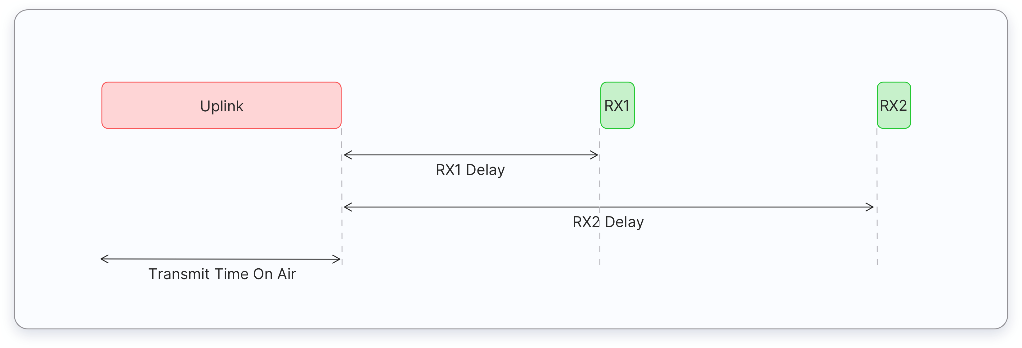
The network server can respond during the first receive window (RX1) or the second receive window (RX2), but does not use both windows.
Class A end devices have very low power consumption. Therefore, they can operate with battery power. They spend most of their time in sleep mode and usually have long intervals between uplinks. Additionally, Class A devices have high downlink latency, as they require sending an uplink to receive a downlink.
The following are some of the use cases for Class A end devices:
- Environmental monitoring
- Animal tracking
- Forest fire detection
- Water leakage detection
- Smart parking
- Asset tracking
- Waste management
Class B
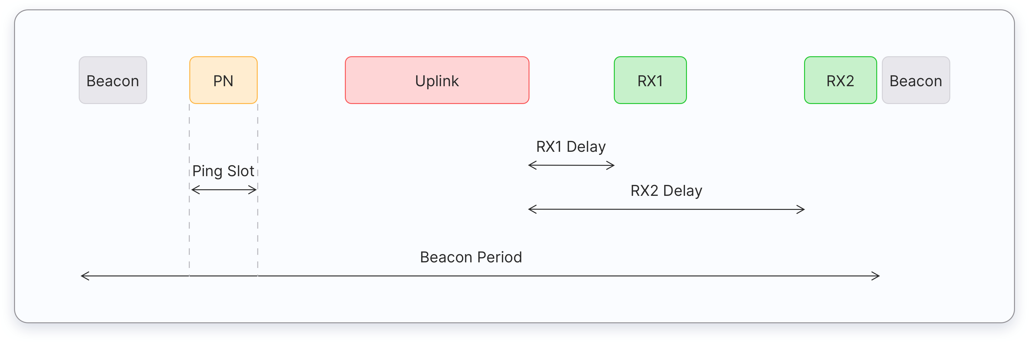
Class B devices extend Class A capabilities by periodically opening receive windows called ping slots to receive downlink messages. The network broadcasts a time-synchronized beacon (unicast and multicast) periodically through the gateways, which is received by the end devices. These beacons provide a timing reference for the end devices, allowing them to align their internal clocks with the network. This allows the network server to know when to send a downlink to a specific device or a group of devices. The time between two beacons is known as the beacon period.
After an uplink, the two short receive windows, RX1 and RX2 will open similar to Class A devices.
Class B end devices have low latency for downlinks compared to Class A end devices because they periodically open ping slots. However, they have much higher latency than the Class C end devices. Class B devices are often battery powered. The battery life is shorter in Class B compared to Class A because the devices spend more time in active mode due to receiving beacons and having open ping slots. Because of the low latency for downlinks, Class B mode can be used in devices that require medium-level critical actuation, such as utility meters.
The following are some of the use cases for Class B end devices:
- Utility meters (electrical meters, water meters, etc)
- Street lights
Class B devices can also operate in Class A mode.
Class C
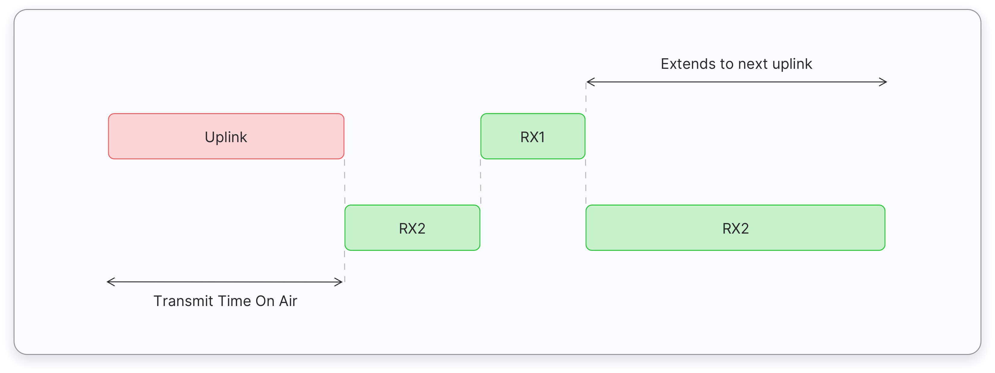
Class C devices extend Class A capabilities by keeping the receive windows open unless transmitting an uplink, as shown in the figure below. Therefore, Class C devices can receive downlink messages at almost any time, thus having very low latency for downlinks. These downlink messages can be used to activate certain functions of a device, such as reducing the brightness of a street light or turning on the cut-off valve of a water meter.
Class C devices open two receive windows, RX1 and RX2, similar to Class A. However, the RX2 receive window remains open until the next uplink transmission. After the device sends an uplink, a short RX2 receive window opens, followed by a short RX1 receive window, and then the continuous RX2 receive window opens. This RX2 receive window remains open until the next uplink is scheduled. Uplinks are sent when there is no downlink in progress.
Compared to Class A and Class B devices, Class C devices have the lowest latency. However, they consume more power due to the need for opening continuous receive slots. As a result, these devices cannot be operated with batteries for long time therefore they are often mains powered.
The following are some of the use cases for Class C end devices:
- Utility meters (electrical meters, water meters, etc)
- Street lights
- Beacon lights
- Alarms
Class C devices can also operate in Class A mode.
End Device Activation
Every end device must be registered with a network before sending and receiving messages. This procedure is known as activation. There are two activation methods available:
- Over-The-Air-Activation (OTAA) - the most secure and recommended activation method for end devices. Devices perform a join procedure with the network, during which a dynamic device address is assigned and security keys are negotiated with the device.
- Activation By Personalization (ABP) - requires hardcoding the device address as well as the security keys in the device. ABP is less secure than OTAA and also has the downside that devices can not switch network providers without manually changing keys in the device.
Over-The-Air-Activation in LoRaWAN 1.1
In LoRaWAN 1.0.x, the join procedure requires two MAC messages to be exchanged between the end device and the Join Server:
- Join-request - from end device to the Join Server
- Join-accept - from Join Server to the end device
Before activation, the JoinEUI, DevEUI, AppKey, and NwkKey should be stored in the end device. The AppKey and NwkKey are AES-128 bit secret keys known as root keys. The matching AppKey, NwkKey, and DevEUI should be provisioned onto the Join Server that will assist in the processing of the join procedure and session key derivation. The JoinEUI and DevEUI are not secret and visible to everyone.
Note:
The AppKey and NwkKey are never sent over the network.The following steps describe the Over-The-Air-Activation (OTAA) procedure.

Figure: OTAA message flow in LoRaWAN 1.1
Step 1
The join procedure is always initiated by the end device. The end device sends the Join-request message to the network that is going to be joined. The Join-request message consists of the following fields.
| 8 bytes | 8 bytes | 2 bytes |
| JoinEUI | DevEUI | DevNonce |
- JoinEUI – a 64-bit global application identifier in IEEE EUI64 address space that uniquely identifies the Join Server that can assist in the processing of the Join-request and derivation of the session keys.
- DevEUI – a 64-bit global device identifier in IEEE EUI64 address space that uniquely identifies the end-device.
- DevNonce – a 2-byte counter, starting at 0 when the device is initially powered up and incremented with every Join-request. The DevNonce value is used to prevent replay attacks.
Note:
In LoRaWAN 1.1 AppEUI is replaced with the JoinEUI.The MIC is calculated over all the fields in the Join-request message using the NwkKey. The calculated MIC is then added to the Join-request message.
Note:
The NwkKey is not sent with the Join-request message, and the Join-request message is not encrypted but sent as plain text.The Join-request message can be transmitted using any data rate and using one of the region-specific join channels. For example, in Europe an end device can transmit the Join-request message by randomly choosing among 868.10 MHz, 868.30 MHz, or 868.50 MHz. The Join-request message travels through one or more gateways to the Network Server.
Note:
No response is given to the end-device if the Join-request is not accepted.Step 2
The Network Server forwards the Join-request message to the corresponding Join Server.
Step 3
The Join Server processes the Join-request message. The Join Server will generate all the session keys (AppSKey, FNwkSIntKey, SNwkSIntKey, and NwkSEncKey) if the end-device is permitted to join the network.
Step 4
If the above step gets success, the Network Server generates the Join-accept message. The Join-accept message consists of the following fields.
| 1 byte | 3 bytes | 4 bytes | 1 bytes | 1 bytes | 16 bytes |
| JoinNonce | NetID | DevAddr | DLSettings | RXDelay | CFList |
- JoinNonce – a device specific counter value provided by the Join Server and used by the end device to derive the session keys, FNwkSIntKey, SNwkSIntKey, NwkSEncKey, and AppSKey.
- NetID – a 24-bit unique network identifier.
- DevAddr – a 32-bit device address assigned by the Network Server to identify the end device within the current network.
- DLSettings – a 1-byte field consisting of downlink settings which the end device should use.
- RxDelay – contains delay between TX and RX
- CFList – an optional list of channel frequencies for the network the end-device is joining. These frequencies are region-specific.
The Message Integrity Code (MIC) is calculated over all the fields in the Join-accept message using NwkKey (for LoRaWAN 1.0 devices) or JSIntKey (for LoRaWAN 1.1 devices) . The calculated MIC is then added to the Join-accept message.
The Join-accept message itself is then encrypted with the NwkKey. The Network Server uses an AES decrypt operation in ECB mode to encrypt the join-accept message.
The Join-accept message is encrypted with the NwkKey (if triggered by Join-request) or JSEncKey (if triggered by Rejoin-request).
Then the Network Server sends the encrypted Join-accept message back to the end device as a normal downlink.
Note:
No response is given to the end-device if the Join-request message is not accepted by the Network Server.Step 5
The Join Server sends the AppSKey to the Application Server and the three network session keys (FNwkSIntKey, SNwkSIntKey, and NwkSEncKey) to the Network Server.
Step 6
The end-device decrypts the Join-accept message using AES encrypt operation. The end device uses AppKey, NwkKey, and JoinNonce to generate session keys.
For LoRaWAN 1.0.x devices,
- AppSKey is derived from the NwkKey.
- FNwkSIntKey, SNwkSIntKey, and NwkSEncKey are derived from the NwkKey.
For LoRaWAN 1.1 devices,
- AppSKey is derived from AppKey.
- FNwkSIntKey, SNwkSIntKey, and NwkSEncKey are derived from the NwkKey.
The end device is now activated on the Network.
After activation, the following additional information is stored in the end device.
- DevAddr - a 32-bit device address assigned by the Network Server to identify the end device within the current network.
- FNwkSIntKey - a network session key that is used by the end device to calculate the MIC (partially) of all uplink data messages for ensuring message integrity.
- SNwkSIntKey - a network session key that is used by the end device to calculate the MIC (partially) of all uplink data messagse and calculate the MIC of all downlink data messages for ensuring message integrity.
- NwkSEncKey - a network session key that is used to encrypt and decrypt the payloads with MAC commands of the uplink and downlink data messages for ensuring message confidentiality.
- AppSKey - a session key used by both the Application Server and the end device to encrypt and decrypt the application data in the data messages for ensuring message confidentiality.
Activation By Personalization
Activation By Personalization (ABP) directly ties an end-device to a pre-selected network, bypassing the over-the-air-activation procedure. Activation by Personalization is the less secure activation method, and also has the downside that devices can not switch network providers without manually changing keys in the device. A Join Server is not involved in the ABP process.
An end device activated using the ABP method can only work with a single network and keeps the same security session for its entire lifetime.
Adaptive Data Rate
Adaptive Data Rate (ADR) is a mechanism for optimizing data rates, airtime and energy consumption in the network.
The ADR mechanism controls the following transmission parameters of an end device.
- Spreading factor
- Bandwidth
- Transmission power
ADR can optimize device power consumption while ensuring that messages are still received at gateways. When ADR is in use, the network server will indicate to the end device that it should reduce transmission power or increase data rate. End devices which are close to gateways should use a lower spreading factor and higher data rate, while devices further away should use a high spreading factor because they need a higher link budget.
ADR should be enabled whenever an end device has sufficiently stable RF conditions. This means that it can generally be enabled for static devices. If the static end device can determine that RF conditions are unstable (for example, when a car is parked on top of a parking sensor), ADR should (temporarily) be disabled.
Mobile end devices should be able to detect when they are stationary for a longer times, and enable ADR during those times. End devices decide if ADR should be used or not, not the application or the network.
LoRaWAN Limitations
LoRaWAN is not suitable for every use-case, so it is important that you understand the limitations. Here’s a quick overview:
Suitable use-cases for LoRaWAN:
- Long range - multiple kilometers
- Low power - can last years on a battery
- Low cost - low cost per node, almost no OPEX
- Low bandwidth - (depending on the spreading factor)
- Coverage everywhere - you are the network! Just install your own gateways
- Secure - 128bit end-to-end encrypted
Not Suitable for LoRaWAN:
- Realtime data - you can only send small packets every couple of minutes
- Phone calls - you can do that with 3G/4G/5G/LTE
- Controlling lights in your house - check out ZigBee or BlueTooth
- Sending photos, watching Netflix - check out WiFi
dB, dBm, dBi and dBd
In this section we briefly discuss some units that are used to measure the performance of transceivers (gateways and end devices) and antennas.
dB (decibel)
The decibel can be used to express the ratio of two physical quantities such as power, sound intensity, sound pressure, voltage, and current on a logarithmic scale. In LoRaWAN we use decibel to express the ratio between two power levels usually given in watt (W) or milliwatt (mW).
The power ratio, N can be expressed in decibel using the formula,
N = 10 log10 (Pout/Pin) dB
where Pout is the output power and Pin is the input power.
Note:
When we are dealing with the power levels we use 10log units.For example, if an amplifier turns a 1 W signal into a 1000 W signal, its power ratio can be expressed as:
N = 10 log10 (Pout/Pin) = 10 log10 (1000/1) = 30 dB
Decibel doesn’t provide an absolute value. By looking at the decibel value you can’t say the input and output power of a device or cable etc, but you can say whether it offers a gain or a loss.
A power ratio greater than 0 dB is treated as a gain. For example, if an amplifier turns a 2 W signal into a 10 W signal, the power ratio is:
N = 10 log10 (Pout/Pin) = 10 log10 (10/2) = 10 log10 (5) = 6.9 dB (gain)
A power ratio less than 0 dB is treated as a loss (negative gain or attenuation). For example, if 10 W of power is fed into a cable but only 8 W is measured at the output, the power ratio is:
N = 10 log10 (Pout/Pin) = 10 log10 (8/10) = 10 log10(0.8) = -0.9 dB (loss)
The power ratio of 0 dB means there is no gain or loss.
dBm (decibel per milliwatt)
If you use the reference input power (Pin) of 1 mW the power ratio, N can be expressed in dBm:
N = 10 log10(Pout / 1) dBm
By using the above formula, Pout can be expressed in mW which is an absolute value.
Antenna gains
The units dBi and dBd are used to express antenna gains.
dBi (decibel relative to isotropic)
The gain of an antenna can be measured relative to an isotropic antenna and is expressed in dBi. An isotropic antenna is a hypothetical antenna that radiates power uniformly in all directions. The gain of an isotropic antenna is 0 dB which means it has no gain or loss.
dBd (decibel relative to dipole)
The gain of an antenna can be measured relative to a reference dipole antenna and is expressed in dBd. A reference dipole antenna offers a fixed 2.15 dB of gain over an isotropic antenna.
The following equation represents the relationship between dBi and dBd:
dBi = dBd + 2.15 dB
Questions:
- Convert 5 dBi to dBd.
XdBd = XdBi - 2.15 = 5 - 2.15 = 2.85 dBd
- Convert 2 dBd to dBi.
XdBi = XdBd + 2.15 = 2 + 2.15 = 4.15 dBi
RSSI and SNR
In wireless communication, a receiver needs a good signal strength and a signal-to-noise ratio to separate the original signal from the modulated carrier. This section contains information about two most commonly used signal strength indicators - RSSI and SNR.
RSSI
RSSI (Received Signal Strength Indicator) is a relative measurement that helps you determine if the received signal is strong enough to get a good wireless connection from the transmitter. Since LoRaWAN supports bi-directional communication, RSSI is an important measurement for both gateways and end devices. RSSI is measured in dBm and its value is a negative form. The closer the RSSI value is to zero, the received signal is stronger.
Apart from the output power of the transmitter, the following factors mainly influence the RSSI:
- Path loss
- Antenna gain
- Cable/connector loss
SNR
SNR (Signal-to-Noise Ratio), often written as S/N, is the ratio of the received signal power to the noise floor. SNR is commonly used to determine the quality of the received signal.
SNR can be calculated using the following formula and is often expressed in decibels (dB):
SNR (dB) = Preceived_signal (dBm) - Pnoise (dBm)
If the RSSI is above the noise floor the receiver can easily demodulate the signal.
Here is a good example of a positive SNR:
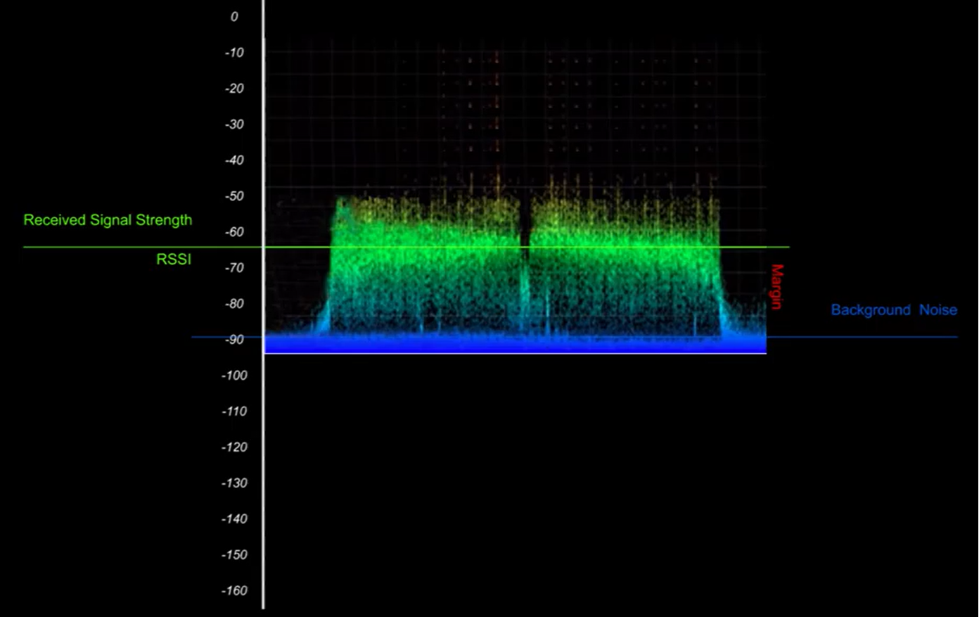
Image captured from the YouTube video by Richard Wenner. The x-axis represents the power level in dBm and the y-axis represents the time.
By looking at the above graph you can see that the RSSI is about -65 dBm and the noise floor is about -90 dBm. By using these values you can calculate the SNR as follows:
SNR (dB) = Preceived_signal (dBm) - Pnoise (dBm)
SNR (dB) = -65 dBm -(-90 dBm) = 25 dB
The positive SNR means that the signal power is greater than the noise power, i.e. the receiver will be able to demodulate the signal.
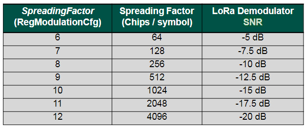
If the RSSI is below the noise floor, it is impossible to demodulate the signal. However, LoRa can demodulate signals that are below the noise floor. The minimum SNR required for demodulation at different spreading factors is shown in the table below:
Here is a good example of a negative SNR:
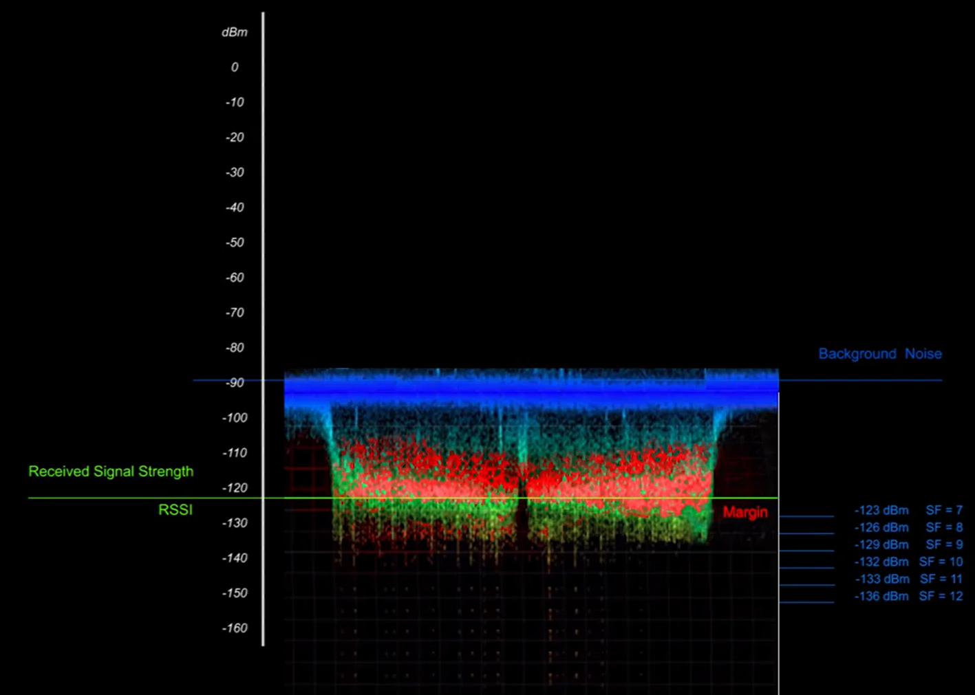
Image captured from the YouTube video by Richard Wenner. The x-axis represents the power level in dBm and the y-axis represents the time.
By looking at the above graph you can see that the RSSI is about -120 dBm and the noise floor is about -90 dBm. Now calculate the SNR as follows:
SNR (dB) = Preceived_signal (dBm) - Pnoise (dBm)
SNR (dB) = -120 dBm -(-90 dBm) = -30 dB
The negative SNR means that the signal power is less than the noise power. The value of -30 dB is below the minimum SNR of -20 dBm @ SF12, so it does not guarantee that the receiver will be able to demodulate the signal.