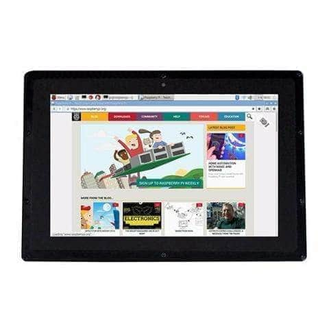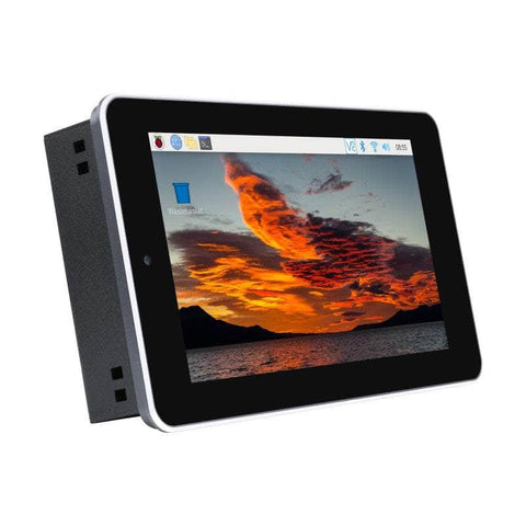


7″ Touch Screen All-In-One Kit for Raspberry Pi CM4, 5MP Camera
7″ Touch Screen All-In-One Kit for Raspberry Pi CM4, 5MP Camera
* The Compute Module 4 is NOT included.
Specifications
| CM4 SOCKET | suitable for all variants of Compute Module 4 |
|---|---|
| NETWORKING | Gigabit Ethernet RJ45 |
| M.2 M KEY, supports NVME SSD | |
| USB | USB 2.0 × 4 |
| CONNECTOR | isolated RS485, RS232, GPIO, and I2C |
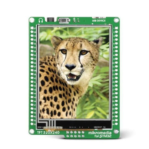
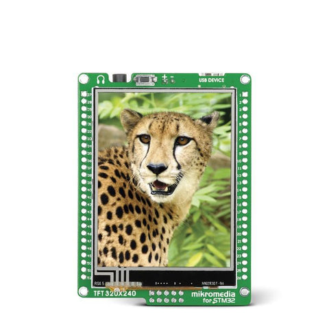
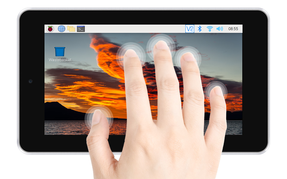
| DISPLAY | 7inch, 800 × 480 pixels, 5-points capacitive touch, toughened glass panel |
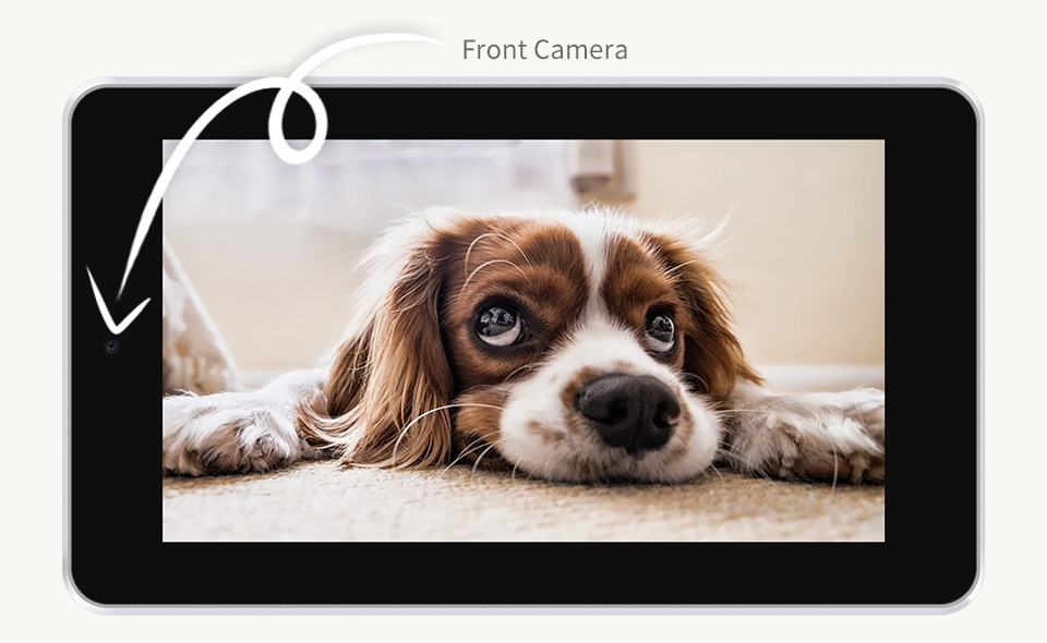
| CAMERA | 5MP, F2.4, 3.89mm fixed focal length, supports video recording |
| VIDEO | HDMI, supports 4K 30fps output |
| RTC | Real-time clock with battery socket and ability to wake Compute Module 4 |
| STORAGE | MicroSD card socket for Compute Module 4 Lite (without eMMC) variants |
| FAN | 5V/12V, allows speed adjustment and measurement |
| SPEAKER | 8Ω 2W dual track speakers |
| POWER INPUT | 7-36V |
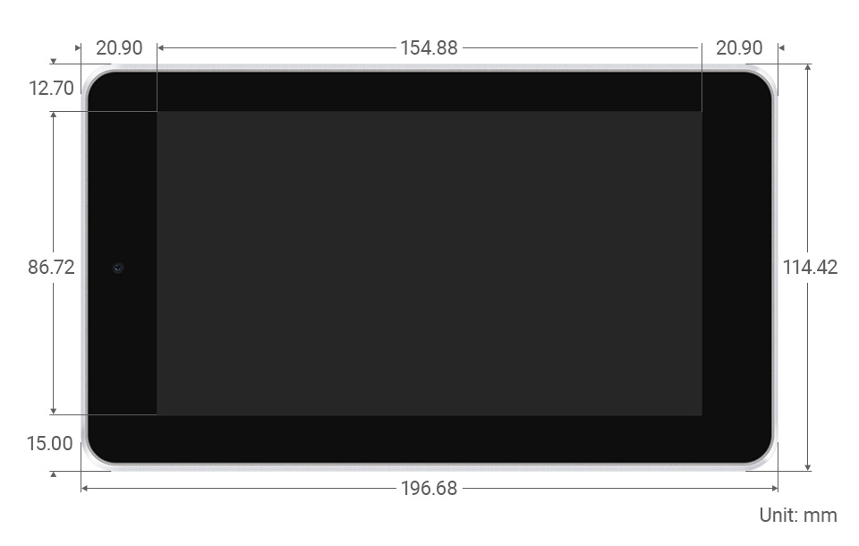
| DIMENSIONS | 196.68 × 114.42mm |
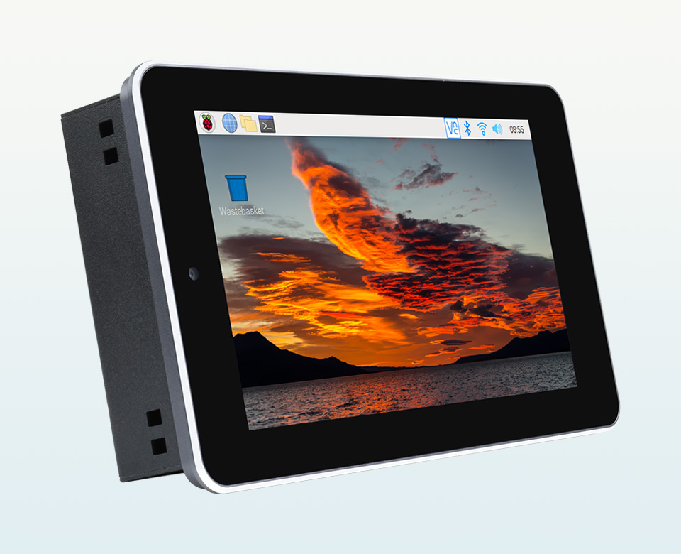
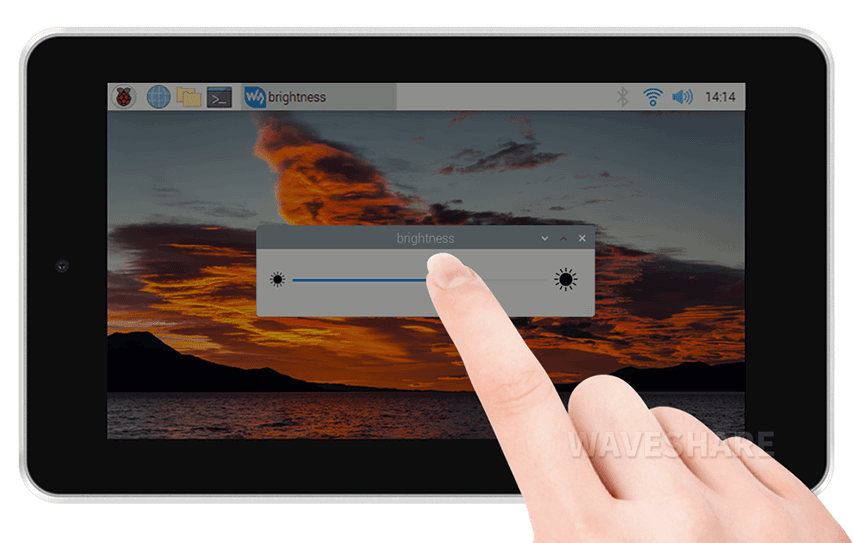
Toughened Glass Screen
7inch Capacitive Touch Screen, 5-Points Capacitive Touch Along With Toughened Glass Panel, More Safe To Use
5MP Front Camera
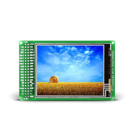
Design Details
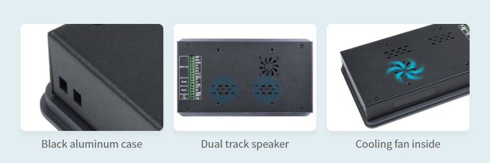
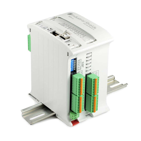
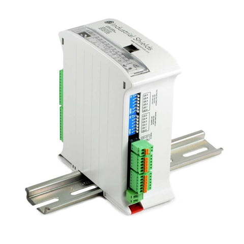
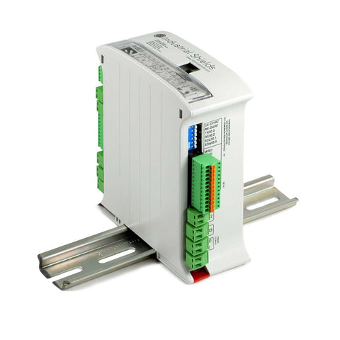
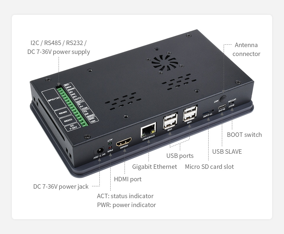
Rich Interfaces
Providing Interfaces Including: CSI, HDMI, USB, M.2, ETH, RS232, RS485
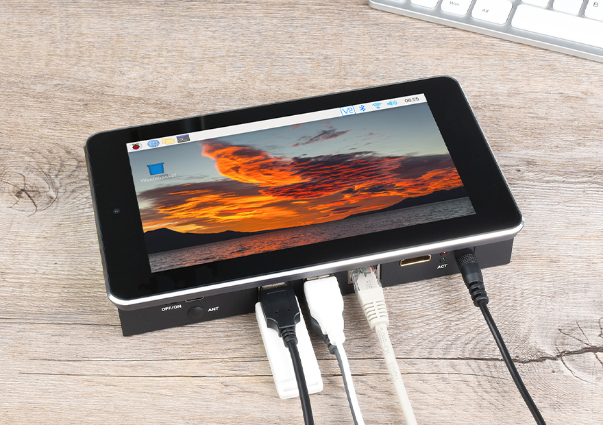
Application Example
Suitable For Raspberry Pi Projects Where Multi Peripherals Are Required, Or Other Industrial Applications
Adjustable Brightness Via Software
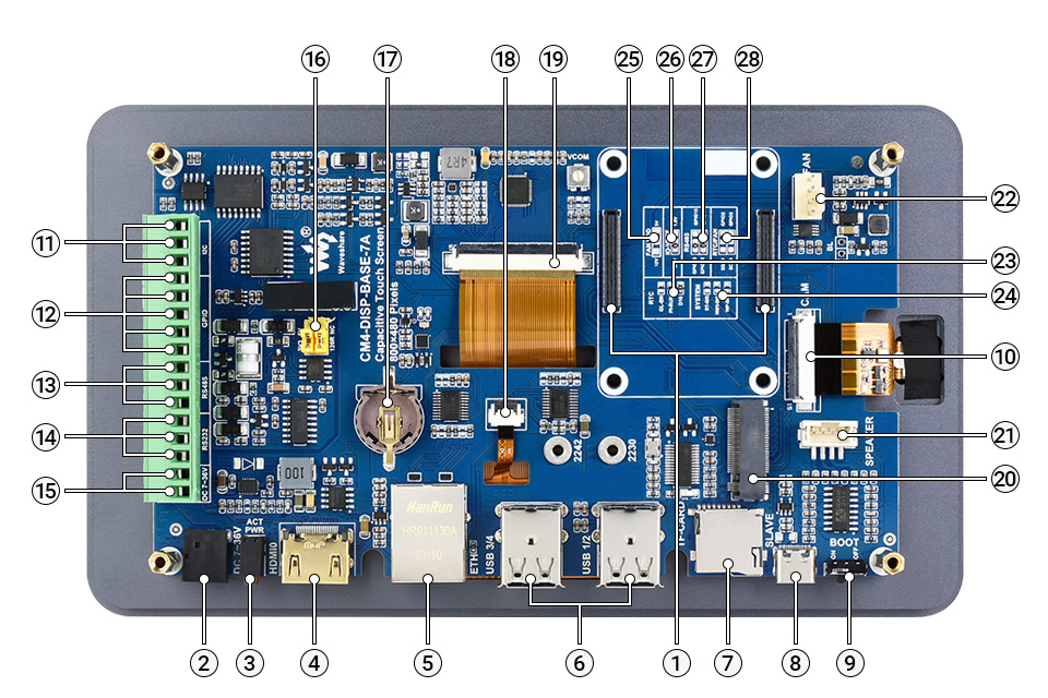
What's On Board
-
CM4 socket
suitable for all variants of Compute Module 4 -
DC power supply
7 ~ 36V DC input -
CM4 status indicator
PWR: Raspberry Pi power indicator
ACT: Raspberry Pi operating status indicator -
HDMI connector
supports 4K 30fps output -
RJ45 Gigabit Ethernet
10/100/1000M compatible -
USB 2.0 ports
4x USB 2.0, for connecting sorts of USB devices -
Micro SD card slot
for connecting a Micro SD card with pre-burnt image (Lite variant ONLY) -
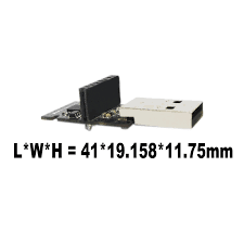
USB SLAVE port
USB programming port -
BOOT selection
ON: CM4 will be booted from USB-C interface
OFF: CM4 will be booted from eMMC or Micro SD card -
MIPI CSI connector
connected to the 5MP front camera -
Isolated I2C
for controlling or reading data from devices via I2C -
Isolated GPIO
for controlling or detecting devices via GPIO - Isolated RS485
- Isolated RS232
-
DC power supply
7 ~ 36V DC input -
RS485 terminal resistor and GPIO logic level selection
RS485: connect/disconnect the 120R resistor
GPIO: GPIO logic level selection
-
RTC battery holder
supports CR1220 button cell -
Touch screen header
connected to the capacitive touch screen -
Display connector
connected to the 7inch 800×480 display -
M.2 M KEY
supports M.2 M KEY NVME SSD, or other communication modules using PCIe channel -
Speaker header
audio output -
FAN header
for connecting cooling fan, allows speed adjustment and measurement -
RTC interruption configuration
GL-EN: CM4 powerdown on RTC interruption
PI-RUN: CM4 will reboot on RTC interruption
D16: D16 pin is triggered on RTC interruption (default) -
System function configuration
BT_DIS: Bluetooth disabled, for CM4 with antenna variant ONLY
WiFi_DIS: WiFi disabled, for CM4 with antenna variant ONLY
WP_DIS: boot mode switch, ONLY be used when NOT booted from eMMC or SD card -
FAN power supply selection
select 5V (default) or 12V power to drive the fan -
IO-VREF selection
set the CM4 IO logic level as 3.3V (default) or 1.8V -
RS485 switch
GPIO13/12: using ttyAMA1 device (default)
GPIO15/14: using ttyS0 device -
RTC/FAN I2C bus selection
SDA0/SCL0: I2C-10 is shared with CSI/DSI
GPIO3/2: I2C-1 is shared with 40PIN GPIO (default)
Outline Dimensions